AM Broadcast Basics


Amplitude Modulation

by Ed Montgomery

This is part one in a series about the basics of amplitude modulation. For continuing education credit, see the information at the end of the article.

Amplitude Modulation — AM — is a broadcast system that seems to have been neglected over the past two decades.

 
Read Other Parts in this Series:

In recent years it has been tagged "Ancient Modulation," and criticized for being full of noise. Many critics have defined it as "low fidelity" when comparing it to FM, and there is some truth to that.

Yet AM has a lot of things going for it. There are more than 4,700 AM radio stations in the United States. The frequency band in which our AM service is located produces a significant groundwave that permits the transmission of reliable signals over a vast area with relatively little power compared to what must be supplied to an FM signal operating in the VHF band. The AM signal travels up and down over hills – obstacles that give VHF signals trouble.

If a new form of digital radio is successful, the AM broadcaster, operating at a frequency with these attributes, has much in its favor.

The medium-wave frequencies on which AM operates also reflect radio signals radiated skyward back to earth. This often causes interference at night. In the early days of broadcasting, the FCC, and the Federal Radio Commission before it, regulated night power and antenna design to limit interference. Night "skip" was something many people actually listened for, attempting to hear programs hundreds of miles away. Some still do, but with so many syndicated talk programs on the AM band at night, the listener often finds the same programming already available in his or her community. Sporting events still have people tuning in to distant stations at night. Clear-channel stations still provide the nighttime service, but it is far less important than it was a half-century ago.

This series is about the basics of amplitude modulation. It will not eliminate the need for a broadcast engineer. It is intended to help make the current generation of broadcasters aware of the equipment for which it is responsible, and to help those managers inspect that equipment periodically to make sure it is operating properly.

Need to know

If you can tell your technical staff of potential problems in an informative way, you enable them to take preventive or corrective measures before the station is obliged to operate at low power, in mono, or shut down.

Radio broadcasting has changed drastically over the past few years. Individuals who entered this career just five or 10 years ago find it to be much different than the labor-intensive business it once was. Management no longer has to make sure someone is at the studio and transmitter site to keep program continuity. Advancements in computer technology allow an operator to keep a radio station operating for days unattended.

While this trend may limit careers for budding DJs and talk-show hosts, it does put more of demand on management. Today’s sophisticated broadcast systems require attention, and often they are neglected until the dreaded "dead-air" occurs. Usually, panic ensues, at which point managers usually start calling on anyone who has any knowledge of the system.

Many stations are not prepared to substitute locally originated material. The announcers are not there, and neither is the programming, be it music or talk. The staff managing today’s radio stations must know something about how the audio and radio transmission system operates.

Deregulation has added to the responsibilities of management. Owners now can own and operate many broadcast properties in a market or adjacent markets. Reliability of equipment has permitted the centralization of studios and reduction in personnel. For better or worse, the technical staff, or traditional broadcast engineer, has been reduced in importance in the eyes of ownership because of improvements in the equipment in a broadcast facility.

New studio and transmitter equipment using computer technology often is beyond the scope of the old "workbench repair" that took place in the past. Often, it is often not in the interest of the broadcaster to purchase the test equipment necessary to make these repairs; often it is not in management’s interest to hire an engineer who understands all these concepts and to keep this person up to date by paying for training when necessary. Engineers don’t like to hear that, but in this age it is true. It is easier to call the manufacturer and get advice than try to troubleshoot on your own.

Normally a transmitter will run, unattended, for long periods of time without trouble. New components today have incredibly long lives. However, when no engineer is on site, management should inspect the transmitter and antenna site periodically. Management should check how the studio system is functioning as well. An individual need not have experience in electronics to detect problems. A person with a good ear and an ability to read meters correctly is an important asset to make sure the station is running without problems. Such an employee may be able to detect problems before they become a serious threat to station operation.

Telephone conversations with the engineer or company contracted to perform maintenance are more informative if they include essential information about audio levels, antenna currents, phase angles and modulation. This will allow the person on the other end of the phone to offer some valid suggestions before making a trip to your station. Often the problem can be solved by phone. The engineer may be able to determine that the equipment must be sent back to the manufacturer for repair. These conversations can also help determine whether the station must notify the FCC about the problem.

In short, even non-technical staff should be aware of the fundamentals of AM radio station operation. We will begin our closer look next time.

You can receive continuing education credit from Northern Virginia Community College as part of this series of articles. All information for this course (BCST504.01N) will be published in this series in RW. For a faxed copy of the registration form, send e-mail to radioworld@imaspub.com or call (703) 998-7600, ext. 117.

Neither Northern Virginia Community College nor Radio World will have back issues or other information regarding this course. You can contact the author for assistance via e-mail at emontgom@lan.tjhsst.edu.


Ed Montgomery is the video technology and communications lab director at Thomas Jefferson High School for Science and Technology, Fairfax County, Va. He has worked as a broadcast engineer and has taught college-level broadcast engineering technology and written educational columns for RW.

Basics of Amplitude Modulation, Part II

By Ed Montgomery

This is the second part in a series about the basics of amplitude modulation. For continuing education credit, see the information at the end of the article.

Amplitude modulation is a simple, efficient method for transmitting information. The original idea for creating a radio signal goes back to James Clerk-Maxwell, an English physicist who theorized the existence of electro-magnetic energy in 1873. His theories were proven by Heinrich Hertz, who actually generated and received radio waves in his laboratory in 1888. Hertz did not follow up his work with any practical applications.

 
Read Other Parts in this Series:

It was Guglielmo Marconi who found the practical application for the "wireless telegraph." Marconi implemented a system of radio communications between ships and coastal stations he had established on land. Most of these systems employed an alternator similar to the one in an automobile to create a radio signal.

The radio wave is the product of an electric current flowing through an unterminated wire or antenna. As the alternating current flows to the end of the wire and then back, a magnetic field is created perpendicular to the current flow. If the wire is spread apart as illustrated in Figure 1 (below), the magnetic field will radiate away from the transmission line.
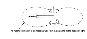
Spreading the wires apart creates an antenna. The radio wave is moving away from the antenna at the speed of light. Originally this magnetic field would be intercepted by the receiver antenna, and through electro-magnetic induction, produce a small current that would actuate a relay creating a clicking sound. Morse Code was sent this way.

But some people wanted to do more than just transmit code. One could say that the frequency that was transmitted with code was the carrier. To transmit voice, more than the carrier had to be sent.

It was discovered that if audio signals were converted to electric current variations, through a microphone, these signals could be added to the radio frequency and decoded in a receiver. Initially these audio signals were capacitively or inductively coupled to the radio frequency. Pioneers like Reginald Fessenden and Lee DeForest demonstrated audio transmissions around the United States and Europe.

However, it was another individual, more closely associated with FM, who improved amplitude modulation and made it practical for broadcasting. Edwin Howard Armstrong invented the principle of regeneration or oscillation. This allowed the alternator to be retired. The totally electronic transmitter was at hand. Armstrong also invented the superheterodyne receiver, making radio reception simple and reliable.

The carrier

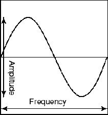
Amplitude modulation operates on a specific frequency known as a carrier. This signal never changes in power. The operating power of a broadcasting station is the carrier power. The radio signal is generated in the form of a sine wave. Figure 2 (below, left) depicts its wavelength and amplitude characteristics. The number of wavelengths occurring in one second is the wave’s frequency, measured in cycles per second, or Hertz.

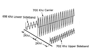
The audio signal is added to the carrier frequency creating modulation. For instance, if the carrier frequency is 700 kHz, the radio signal, or carrier, is creating magnetic fields that are radiating off the antenna at 700,000 times per second. If audio is applied to this carrier, the sum and difference frequencies also will be transmitted. If an audio tone of 2,000 cycles is applied to the carrier, the following frequencies will be present:

Audio Frequency: 2,000 Hz

Carrier Frequency: 700,000 Hz

Sum Frequency: 702,000 Hz

Difference Frequency: 698,000 Hz

The antenna will accept the frequencies that are most closely related to the carrier: 698 kHz, 700 kHz and 702 kHz. The 698 kHz and 702 kHz are sidebands. The difference between the carrier and sideband frequencies is the audio frequency. It is duplicated above and below the carrier.

Figure 3 (above, right) depicts the sidebands and the carrier. The amplitude of the sideband determines the loudness of the signal while varying frequencies in the sideband represent the audio information. For years, radios used a diode or envelope detector to extract the audio from the radio signal and amplify it.

Much of the problem with AM broadcast today is not within the transmission of the signal but in its reception. Most electro-magnetic noise, from lightning, motors, computers, etc., is an amplitude function. Because the AM receiver is detecting amplitude variations, it receives the desired signal along with any other electro-magnetic noise in the vicinity.

Remember the radio signal is very weak. Signals from computers, telephone systems, appliances, and so many other local sources are much stronger. The receiver picks up everything surrounding the carrier and amplifies it, often producing a lot of noise.

Over the past 30 years, receiver manufacturers have tried to reduce noise by narrowing the frequency bandwidth of the tuner.

AM transmits a frequency response that is very close to human hearing. It is flat out to 7,500 Hz and beyond. However, audio is varying constantly, allowing noise to get in where low levels of radio signal are present. The receiver manufactures decided to cut the audio bandwidth to 2,500 to 3,000 Hz. This reduces fidelity.

There are other methods available to reduce noise in AM while keeping audio fidelity high. One is to replace the envelope detector with a synchronous detector. That was once an expensive addition, but now simply requires a microprocessor. Receivers with AM stereo capability use them with good results. Many automobiles have them. They do not eliminate noise, but they reduce it.

Denon has made a receiver sold by the NAB that has a "smart filter" that will eliminate a lot of noise. However, few consumer stereo manufacturers have chosen to add this feature in their AM receivers. Even the ingenious Bose wave radio, which uses a synchronous-type of detection circuit, has no provision for decoding a stereo signal.

We will continue the discussion in our next part.


You can receive continuing education credit from Northern Virginia Community College as part of this series. The course fee is $30, payable to the college. For a faxed copy of the registration form, send e-mail to radioworld@imaspub.com or call (703) 998-7600, ext. 117

Ed Montgomery is the video technology and communications lab director at Thomas Jefferson High School for Science and Technology, Fairfax County, Va. He has worked as a broadcast engineer and college-level instructor. Reach him at emontgom@lan.tjhsst.edu

The Basics of Amplitude Modulation: AM Fights Its Own Success

By Ed Montgomery

This is the third part in a series about the basics of AM radio.

The critical situation AM finds itself in today is really a product of it being a successful broadcasting system. It can reproduce a broad range of audio frequencies approaching human hearing, and in the golden days of radio, it was quite a medium.

 
Read Other Parts in this Series:

In the 1930s and ’40s there were far fewer radio stations on the air, producing far less co-channel and adjacent channel interference. Primary service areas received a strong signal with little local interference to compete with the radio signal. Receivers were designed with radio frequency circuits that were broad enough to receive the entire signal.

Life was good for AM. I grew up in the New York metropolitan area, where there were eight 50 kW AM stations. These signals were so powerful that lightning often caused only a small crackle to the audio.

After World War II there was a demand for more broadcasting stations for smaller communities. The FCC reduced interference standards, resulting in thousands of new stations. Many were awarded licenses for daytime-only operation, while others were given full-time authority. Many had narrow directional patterns, a scenario that fit the audience of the times, far less mobile than that of today.

The addition of stations from the 1940s until today created problems for receiver manufacturers. Receivers were no longer picking up clean signals free of whistles (heterodynes) and adjacent channel audio. The solution was to narrow the bandwidth of the received signal. This has been done to the point where now AM, on some of the best tuners available, sounds like it is being received over a telephone line.

Interference was solved – at the expense of fidelity.

AM stereo was an ingenious idea that actually improved the sound quality of AM, giving it depth. Those who have heard it know. Unfortunately, the system never got off of the implementation stage with few receiver manufacturers making radios. I always thought a great disservice was done to AM in the way stereo development was handled by the FCC, the inventors, receiver manufacturers, and even the broadcasters. It has been an opportunity lost, in my opinion.

AM transmission equipment is still capable of doing what it did 50 years ago. Most receivers are a shadow of their ancestors when it comes to reproducing the signal. The technology is there to improve fidelity, but most consumer receiver manufacturers fail to take action. In fact, many FM receivers don’t approach the quality FM broadcasters are transmitting.

Audio levels are extremely important for AM broadcasters. The strength of the power in the sidebands creates the "loudness" of the signal in the receiver. It is important to have a strong signal to overcome as much noise as possible.

Audio levels are observed in the studio by monitoring the VU meter. Located on the audio console, this volume unit meter measures the electrical strength of audio signals being broadcast.

The console receives signals from microwave remote broadcasts or satellite services as well as from the studio and combines or chooses them from local broadcasting. The VU meter measures signal strength in decibels. This a logarithmic measurement that responds to sound the same way our ears do. The ‘0’ level on the VU meter is the optimum operating level.


Reaching your peak

Audio quality starts in the studio. To reproduce audio properly, it is important to have the VU meter readings peak around 0 or +1. Because audio varies constantly, the signal level should be monitored to make sure that the loudest audio is at this level. Do no listen with your ears; observe with the meter. Monitor speakers can be deceiving; the audio system can be checked with calibrated signals from audio oscillators, test CDs and tapes providing a ‘0’ level to make sure the console is operating properly. Along with attenuators that adjust the signal, consoles also have trim adjustments to make sure levels are accurate. Trim adjustments also allow for a balanced output of stereo consoles.

It is important to make sure that the material recorded for broadcast is prepared in a proper manner. If audio is recorded improperly in either a digital or analog format, problems will occur. Recording at an insufficient level will permit the introduction of noise. Recording at an excessive level of about +1 dB will cause distortion and loss of dynamic range, the ability to capture audio in its proper range. Every source of audio that emanates from the console should produce the same peak levels, giving the listener a "feel of continuity" from one segment to the next.

If the station is broadcasting in AM stereo, make sure the channel phasing is correct. Most stereo consoles include left, right and sum or mono VU meters. If you receive material recorded out of phase, or a problem occurs within the studio that causes the left and right channel to be out of phase with each other, the signals that are common to both channels will be canceled out. That will cause problems for your listeners, because most AM receivers are monophonic.

In most instances, a phase problem will cause significant loss of signal because the majority of any stereo signal has components common to both channels. When signals are out of phase, the left and right meters of a stereo pair will appear to read normally, but the mono meter on your mixer will drop to zero.

VU meters can also be used to trace hum and noise. For example, if a VU meter will not return to its resting place, it may indicate an unwanted signal in the system. This can be traced by removing audio from the console and turning up the audio monitor. Increasing and decreasing the levels of individual channels along with cutting off inputs can pinpoint the location of the problem; it can be within the console or an external source.

Another important instrument, though not required, is the modulation monitor. It allows you to see what the signal looks like after it has been transmitted, measured in percent as well as dB. It should be as readily accessible as the console’s VU meters.

Please note: In the previous part of this series on Feb. 3, the graphic captioned Figure 3 contained an error. The center waveform is the carrier, and should have been labeled "700 kHz Carrier Frequency."


You can receive continuing education credit from Northern Virginia Community College as part of this series. The course fee is $30, payable to the college. For a faxed copy of the registration form, send e-mail to radioworld@imaspub.com or call (703) 998-7600, ext. 117

Ed Montgomery is the video technology and communications lab director at Thomas Jefferson High School for Science and Technology, Fairfax County, Va. He has worked as a broadcast engineer and college-level instructor. Reach him at emontgom@lan.tjhsst.edu

The Basics of Amplitude Modulation: Audio Preparations for AM Radio

By Ed Montgomery

This is the fourth in a series of articles about the fundamentals of AM radio.

Audio is a variable: It constantly changes and creates the power levels in sidebands. Because noise is an amplitude function, it is important to create a power level that gives the best signal-to-noise ratio that can possibly be attained.

 
Read Other Parts in this Series:

Audio can come from any number of digital or analog sources. It must be delivered to the transmitter at a level that will give the maximum sideband power possible without adding distortion or reducing dynamic range to an intolerable level. Overdriving the signal at the studio console can cause clipping distortion. Once distortion is introduced into the system, it cannot be removed.

After the signal leaves the studio, it travels either across the building to the transmitter or through a studio-transmitter link (STL), telephone line or microwave feed to the transmitter location.

The audio is prepared for the transmitter by using compressors or limiters to prevent distortion and overmodulation. Often it is wise to use a limiter on telephone lines or microwave STLs to prevent distortion. Unlimited instantaneous peaks can cause undesirable affects.

All transmission systems have a specific operating level, usually related in decibels, which should not be exceeded. The amount of protection necessary is dictated by the type of format being used. Conversations with the engineers in charge of the station can assist you on arriving at a level that is appropriate for your station. If your station does not sound as good as others in your market, assume something is wrong.


Masking noise

Audio processing developed rapidly in the 1950s. After television took away many radio audiences, broadcasters adopted the DJ format, becoming music or news stations. To hold onto listeners, they made the station appear loud. Limiters and compressors were introduced to increase loudness at the expense of some dynamic range, which reduced the appearance of noise within the system.

Another technique to increase loudness and coverage area was the introduction of reverberation. Many stations put these devices at their transmitter sites, adding an echo effect to the broadcast signal. This gave the DJ a louder and more commanding voice. One might say everything sounded like it was happening in a large bathroom, but it worked. Music performers – such as Phil Spector – began to add echo to their songs. Spector’s "wall of sound" recordings were made with the AM band in mind.

The sound of an AM broadcasting station is dependent upon everything from the quality of the studio console to the condition of the antenna system. AM is frequency-sensitive; sideband power is directly related to the audio frequency creating the modulation.

The most powerful sidebands are closest to the carrier. Check the frequency response of the audio line, telephone line or STL. Don’t assume everything is okay. There was a time when the FCC required this in the form of the audio proof-of-performance. A flat frequency response in the audio line can translate into a louder audio signal in the receiver.

Format plays an important part when considering the amount of audio processing being used. You also have to consider what type of receiver people will be listening on. AM listening takes place in cars probably more than any other place. It is important to prepare a signal that will be able to compete with all of the other sounds around the vehicle.


Chemistry set

Processing must not be to the point where "listener fatigue" is reached. Compressors and limiters can be set so the modulation meter almost constantly remains at 100 percent. While this will produce an audio signal almost void of noise, it will also annoy the listener. It usually takes some experimenting with an audio system to get it precisely where you want.

Classical music, which contains many audio levels and variations, requires little audio processing. For that reason, classical music is difficult to carry on AM in this age. At times, the classical station listener might think the station is off the air. Popular music is different and can be processed at a more aggressive level, as its dynamic range is much smaller.

For talk radio, audio should be set somewhere between what is best only for voice and music. Commercial material may include jingles and short music pieces, and they must sound right when broadcast. The "attack time" of the compressor/limiter should not be set to increase the audio output level at the instant someone stops talking. It is important to read the manuals on proper setup of these units to achieve the sound you and your listeners want.

The compressor/limiter has become quite a sophisticated piece of equipment over the years with features that include audio compression, expansion, limiting, clipping and gating. Many models are multiband, permitting specific processing at prescribed frequencies.

When choosing an audio processing system, know that all systems do not interface favorably with each other. A certain manufacturer may say its processor will improve your audio with documented evidence from other broadcasters. While this may be true, you still need to test a unit in your audio chain. Install a demonstrator unit according to the manufacturer’s instructions and listen to it under differing conditions: in a car, on a Walkman, at home, etc. Make sure it is performing to your expectations.

An equalizer may be used to enhance certain frequencies, but this device really "unequalizes" your signal by lowering the output of some frequencies while increasing others. Some broadcasters attempt to use an equalizer to improve the frequency response of an AM station that has a deteriorating antenna system. This is not recommended. The equalizer is best used in the production studio to improve the sound of poorly recorded audio, perhaps to remove unwanted hum from a remote feed. It is not recommended as a part of the studio to transmitter audio chain.

I am probably the last person in America to say this, but I will: AM stereo is a way to improve the sound of AM. I recently researched AM formats and found that more than 75 percent of national AM stations program a substantial amount of music. AM is not the news/talk world that seems to dominate the major markets. AM stereo is worth the investment.


You can receive continuing education credit from Northern Virginia Community College as part of this series. The course fee is $30, payable to the college. For a faxed copy of the registration form, send e-mail to radioworld@imaspub.com or call (703) 998-7600, ext. 117

Ed Montgomery is the video technology and communications lab director at Thomas Jefferson High School for Science and Technology, Fairfax County, Va. He has worked as a broadcast engineer and college-level instructor. Reach him at emontgom@lan.tjhsst.edu


The "reversed form" (negative solution) of Maxwell's Fourth Equation, states that a magnetic field can be produced without current flowing in a wire.

A Working "Crossed–Field" AM Transmission Antenna Using This Principle

The Crossed–Field Antenna Theory by Maurice C. Hately & Ted Hart
link to antenneX Online Magazine

When is a Quarter Wave Not a Quarter Wave?

Maxwell's Equations in Magnetic Media

The Electric Force - The Magnetic Force - Gravity

Site Link List - Element List - Hydroculture Salts

The Tortoise Shell Life Science Puzzle Box Front Page