
Megasquirt-II programmable EFI with coil per plug programmable ignition
So, after driving the car for a few trouble free years with my original megasquirt install (which I'll call MS-I), I finally got going on adding programmable ignition. As I mentioned, ignition timing with this motor has been an ongoing journey. With MS-I the idle was better despite the lumpy cam, but a big part of smoothing it out more is fully mappable ignition control. I also didn't have enough advance at highway cruise speeds with small throttle openings. The engine would jerk slightly, also known as 'trailer-hitching' because it feels like you're pulling a trailer with a loose hitch. I was using the high-resolution code for finer fuel control at idle. When people integrated EDIS ignition to the MS-I hardware, it didn't use this high resolution code branch. I really liked the EDIS concept -- it uses a volume production (i.e. cheap and readily available), hardened, under-hood module that reads a crankshaft position sensor and fires two coils in a 'waste spark' configuration. You can connect the module, sensor (with 36-1 crankshaft wheel), and coils up and it will run all by itself at 10 degrees of advance. One wire is used to command the EDIS module to provide up to 60 degrees of advance by sending the EDIS module a variable width pulse. Since the EDIS system uses a crankshaft position sensor, all the slop in the timing chain, gears, cam/distributor gears, and distributor bushings/advance mechanism itself is also gone and no longer affects the timing accuracy. This can be a lot more slop than you think! More EDIS info is here
When the megasquirt group started working on Megasquirt-II, it seemed to be the way to go. MS-II uses a different microprocessor with more resources that allow it to do high resolution fuel control and ignition control. This new processor is on a small circuit board that plugs into the megasquirt ECU assembly in place of the original processor. Ford EDIS ignition hardware is supported by MS-II.
I'm now using a v2.2 megasquirt main board with the following modifications for my install:
- Added a jumper wire from JP1 pin 6 to +12V at D9 (banded end). This supplies +12V to the idle speed stepper motor driver IC on the MS-II board. Even though I'm not using this (the aux air regulator is still working great), it is needed to keep the driver chip's power consumption down. Details here.
- Implemented the EDIS ignition input and output changes detailed here for my v2.2 board. I'm using step 1a (the FIDLE output option) to send the ignition advance (SAW) signal buffered through the 'idle solenoid' drive transistor Q5 to the EDIS module. This avoids connecting the microprocessor pin directly to the outside world. I also implemented step 2 which configures the ignition input circuit.
That's it for the ECU changes. I installed the v3.01 megasquirt-II board, and checked it out on the stimulator. Everything looked great.
Of course, I could have just installed the Ford EDIS module, crankshaft sensor, toothed wheel, coil pack and plug wires and been done with it. But it was winter here in Minnesota, and I had time and some BMW coils on my hands and I experimented with using the EDIS module to drive the individual coils. First, I built a test bench using an idea from Bruce Bowling and Al Grippo to use a small microcontroller to generate the crankshaft position sensor signal. This was easier for me than rigging up a variable speed drive to spin the toothed wheel and mount a sensor. I used a Motorola (now Freescale semiconductor) demonstration board (available from Digi-Key, part# M68DEMO908QT4), and modified Bruce and Al's code to work on it.
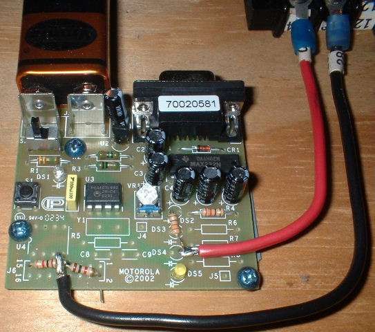
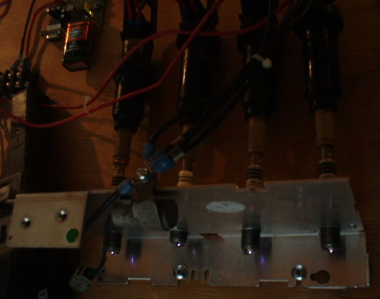
Here's a pic of everything together with some tachometers test equipment connected. First, I looked at what the coil behavior was with the Ford Escort coilpack. The coils charge to 6 amps in about 4.1mS. This dwell time varies depending on battery voltage, but the 6 amp (approx.) threshold remains the same.

Next I connected some 'dumb' (no internal igniter) BMW coils in place of the Ford coilpack. I used coils that are on most 6/8/12cyl late model BMWs from late 2002 on up, such as a 2003 745i. BMW part number is 12131712219, list price about $31 each. The coils have a triangular connector. The top terminal (4a) is secondary ground, lower left terminal (15) is +12Vin, and the lower right terminal (1) connects to the EDIS coil driver. These charged to the same 6A threshold in about 2.1mS -- or almost half the time of the Ford coilpack. The wheels started turning in my head, what would happen if I connected two COP coils in series, which doubles their inductance and thus the charge time. Eureka! It worked; the charge time was just slightly longer than with the Ford coilpack. And if I installed one pair of coils in cylinders 1 and 4, and the other pair in cylinders 2 and 3, they would fire in a 'waste spark' configuration just like the Ford system, and I'd be driving the 4 coils with only one EDIS module. Others looking at using COP coils were paralleling two EDIS modules to get the capacity to drive 4 coils. (Each EDIS-4 module has two coil driver outputs).

And here's my mixed bag of test plugs firing:
Now that I had the ignition working on the bench, the next step was to get the '02's tach to work with the new ignition. I tried the circuit at the bottom of this page. It seemed to be fine at first, but then when I disconnected my test equipment it no longer worked. The fix was to put a 100k ohm resistor across one of the coil diodes (either D1 or D2), and the tach stayed happy.
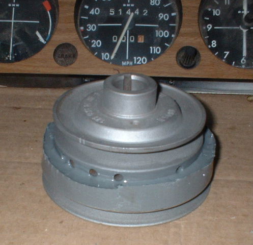
All of my Ford EDIS parts came off an early/mid 1990's Escort with the 1.9l SPFI engine. This motor is pretty distinctive in the junkyard; it has an intake manifold that is fabricated from aluminum tubing, not a casting. The EDIS module is behind the left headlight, mounted to the engine compartment fuse/relay block. The coilpack is mounted to the cylinder head, and the pulley/sensor is behind the right wheel well fender liner. The sensor is secured with T27 torx machine screws. Grab the entire crank pulley assembly; if you look closely you can see that the toothed wheel portion is a powdered metal piece that is pressed on to the pulley. Open a big vise until it supports the toothed wheel, and tap the center of the pulley to separate them.
I bead blasted the 2002 front pulley to get it good and clean, then made a 'dam' from duct tape around the outside diameter of the big front-most (on the engine) groove.
Fill the area around the middle groove with J.B. weld, let it harden, remove tape:
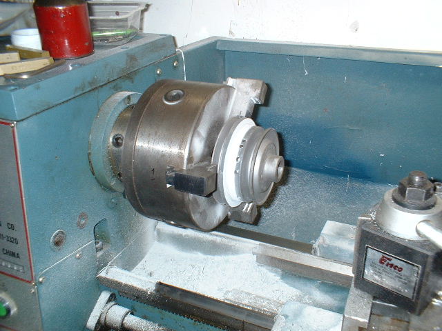
Chuck it up in your neighbor's lathe and turn it down to the EDIS toothed wheel inner diameter, centered over the middle '02 pulley groove. There's a drawing on the megasquirt.info site of the EDIS wheel dimensions somewhere. J.B. weld machines like butter, any small machine shop can do this for you if you don't know someone with a lathe. It machines so easy, I'm sure a better MacGyver than I can figure out a way to do it without the lathe.
Wheel and pulley ready for assembly:

Assembled:

I buttered up the mounting area with some more JB weld, and assembled the toothed wheel. Then I added another fillet of JB weld on the 'back' side of the pulley. Make sure to verify the correct position of the missing tooth before final assembly.
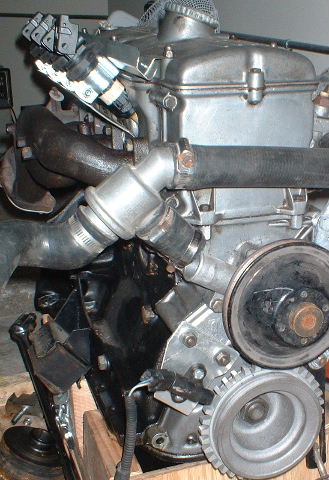
Mounted to an engine:

The pulley was painted before installation on the car. I also added timing marks to the pulley for TDC, since my front cover has a pointer on it still. The sensor mounting bracket is visible in this picture too. It is made from 1/8" thick aluminum and mounts to two of the water pump bolts. A slight bend centers the sensor over the teeth. I set it up with a 0.050" gap between the sensor and the teeth.
I found that a 3/4" conduit clamp would secure the body of the coil well. I made a sheet metal bracket to hold the conduit clamps (and thus the coils) in the proper orientation and secure them to the valve cover studs. The wiring also fits nicely in the bracket channel.

Another view of the ignition parts test fit on a spare engine:
By bending the stock EDIS module mounting bracket a bit more it bolted up to the original '02 coil location. I wired everything up except the COP coils, and then realized that I'd have to connect up the Ford coil assembly in order to verify the timing and sensor position. You can't connect a timing light up to a COP coil! (At least I can't with the light I have.) I hooked it up, temporarily mounted above the charcoal canister at the front of the passenger side of the engine compartment. The motor fired right up, and the base timing was 8 degrees. This means my sensor position relative to the missing tooth (that I eyeballed) was 2 degrees off since the EDIS module defaults to 10 degrees. So, I've programmed a 'Trigger Offset' of -2.0 degrees in the MS-II ignition configuration to 'fix' it in software. Then the COP coils, bracket, and associated wiring were installed. I used insulated female spade terminals to make the connections to the coils, Digi-Key part number A27797-AD. If anyone finds the BMW part number for just the coil connectors, please let me know. The terminals are quite secure, but I'd do something else if they were in an application where they could get exposed to water or other contamination.
The system has been installed and running since the spring of 2005. It really runs great and made another tremendous improvement in performance, drivability, smoothness, and even fuel economy. I'm running more advance at low throttle cruise (40 to 45 degrees) and on a road trip to Chicago with another 2002 with a similar motor got substantially better fuel economy. We both filled up together and drove in a pack through the city of Chicago, then over 100 miles on the highway at 75 MPH. My car got 30 MPG and still had 1/3 of a tank of gas left when the other car was getting down to fumes. He was running a Weber 32/36 carb and a distributor, but had a similar cam, compression, and headwork.
More info at:
Email me at: tskwiot at hotmail dot com.
Follow this link to return.
Last updated Jan 15, 2006
Disclaimer: There is no guarantee of accuracy or completeness of the information provided at this site. You expressly agree that the use of this information is at your sole risk.